Sheet metal projects connect the flat pattern to a finished component. Hole placement, bends, joining and surface treatment should be reviewed as a complete sequence. A drawing package that identifies material thickness, bend direction and finished dimensions makes that review more useful.
At A Glance
| Review area | Typical considerations |
|---|---|
| Cut features | Profiles, holes and slots |
| Formed geometry | Bends, flanges and finished envelopes |
| Joining | Fasteners, inserts or joining requirements |
| Final appearance | Coating, cosmetic faces and protective packaging |
Define the finished condition
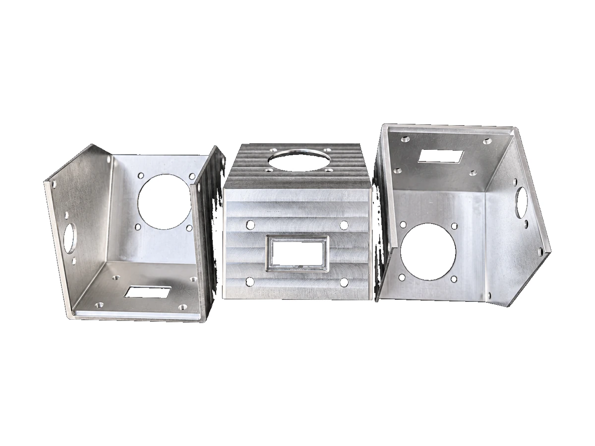
Clarify whether dimensions apply to the flat pattern or the formed component. Include bend direction, material thickness and the surfaces that control assembly. Where a flat pattern is supplied, make its relationship to the finished model explicit.
Review bends and nearby features
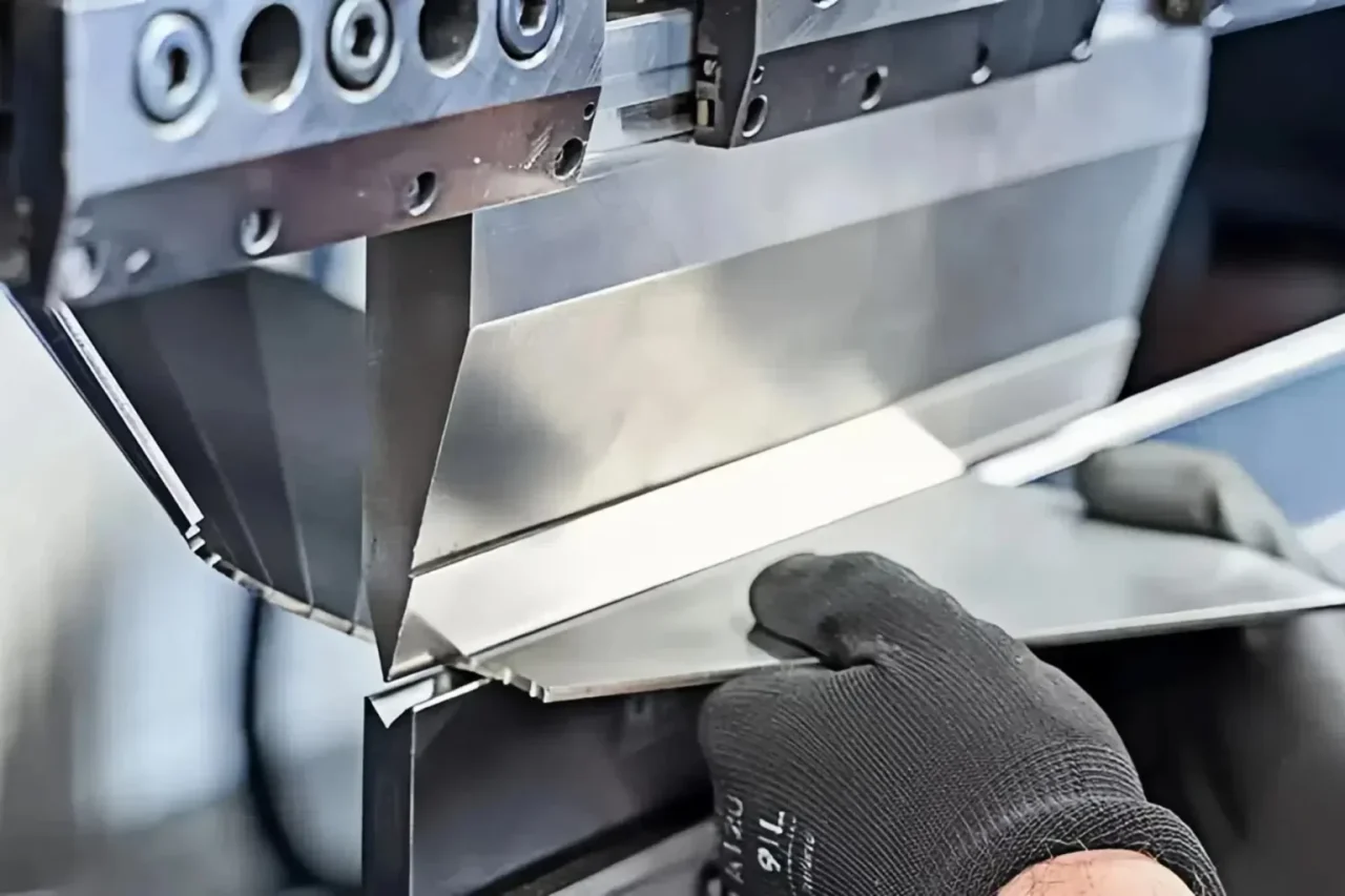
Features close to a bend need particular attention during process planning. Provide the intended bend radius and identify any fit-critical holes or slots. The manufacturing review should resolve the tooling approach before the design is released.
- Provide both formed CAD and available flat-pattern data
- Specify material grade and thickness
- Identify visible faces and required grain direction
- List inserts, fasteners and joining details
Plan coating and assembly together
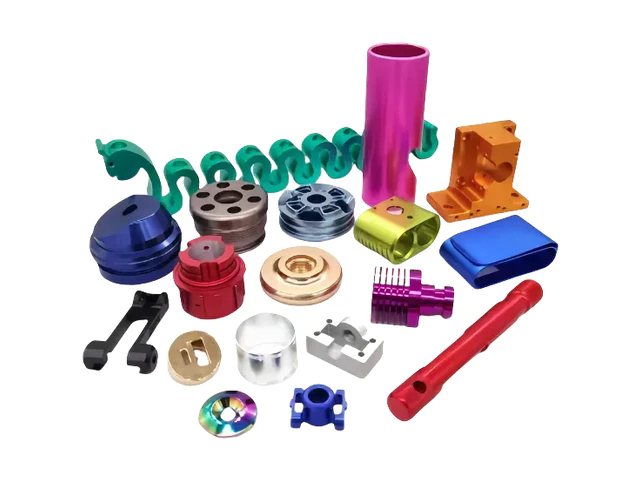
Coating allowances, masked holes and mating surfaces should be documented. For assemblies, define which dimensions and visual surfaces will be checked after finishing and joining.
Frequently Asked Questions
Is a flat DXF enough?
It may describe the cut profile, but a formed drawing or model is needed when the component includes bends, joining or assembly requirements.
Can finishing be included in the review?
Yes. Specify the required finish, color reference, masking and acceptance criteria when requesting the quote.